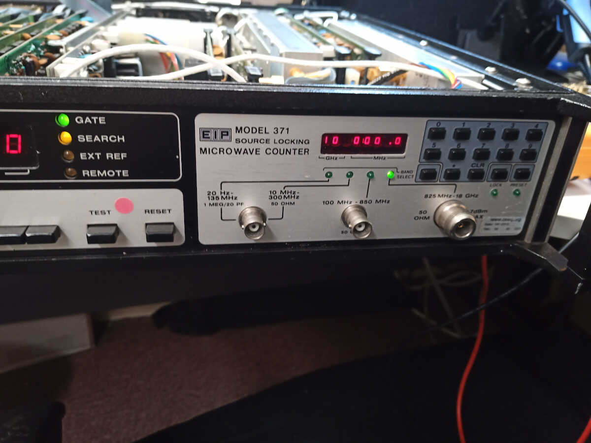
EIP 371 Microwave Frequency Counter
Problem
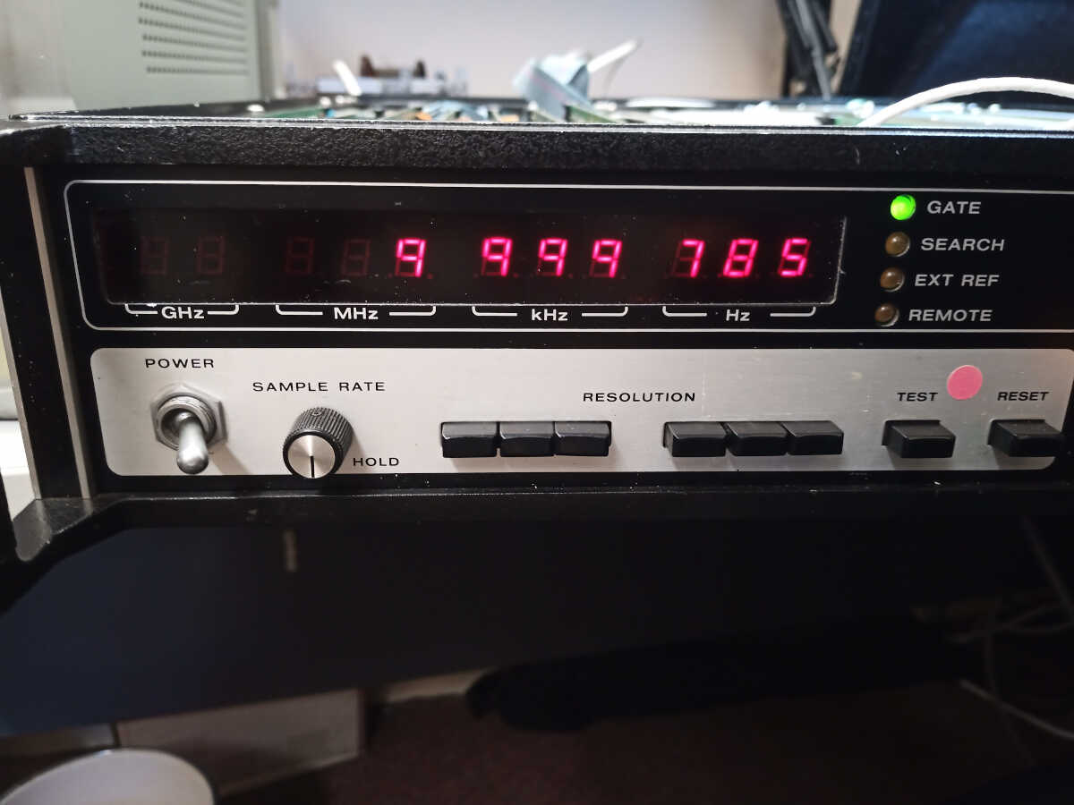
An EIP microwave frequency counter would not function, on first power up the display was not working correctly, only some digits lit up and all the band selection LEDs were lit simultaneously.
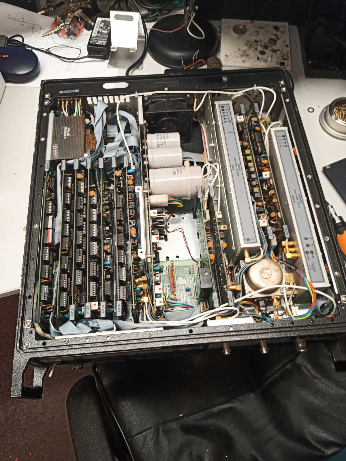
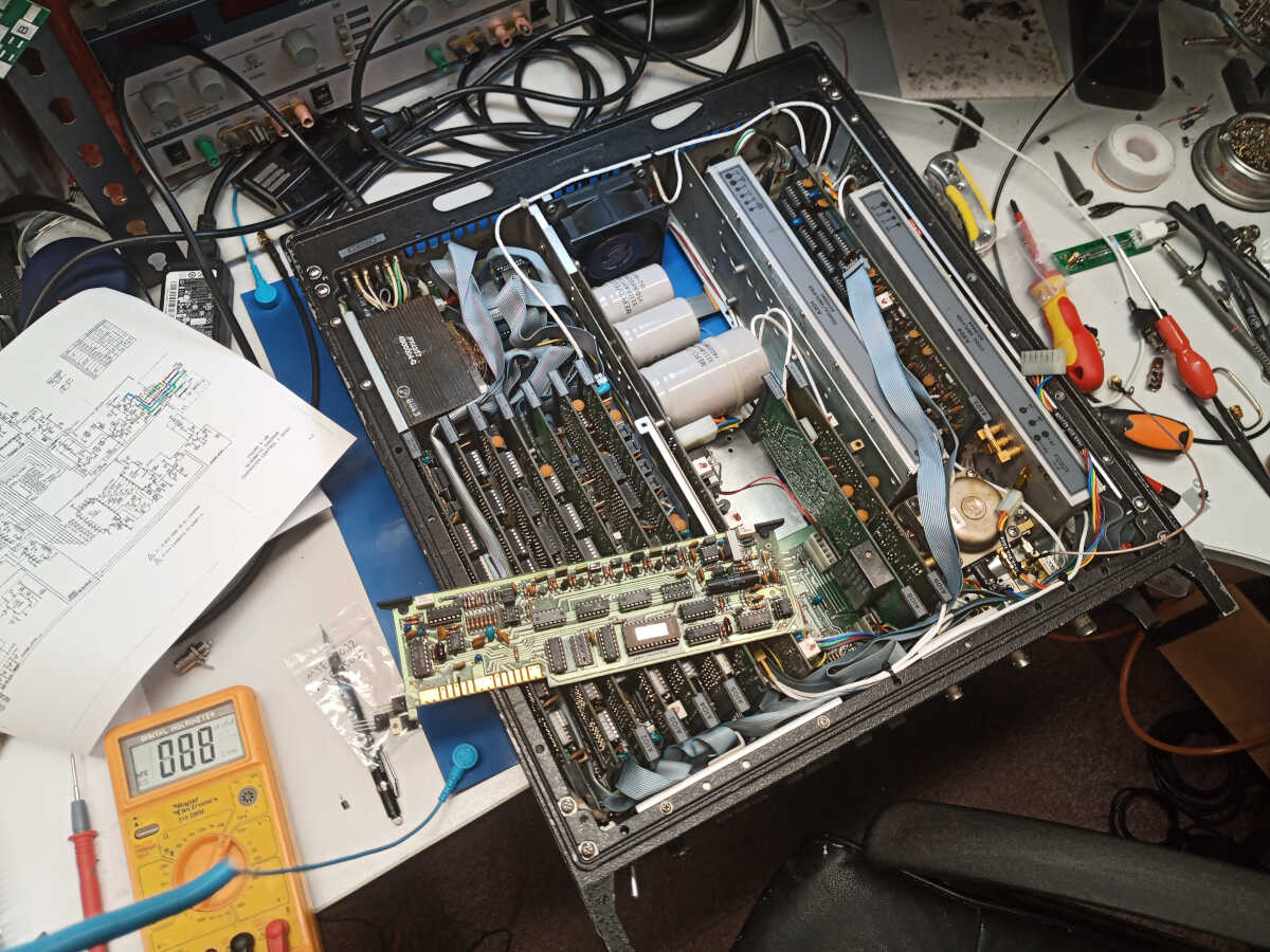
Checking inside the unit revealed a very modular construction which made it easier to investigate the fault, one board at a time.
Diagnosis
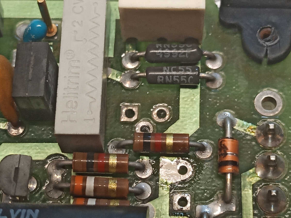
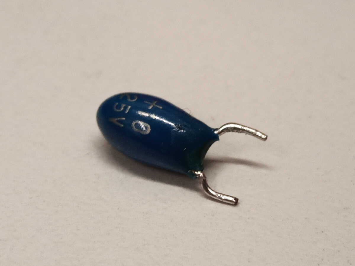
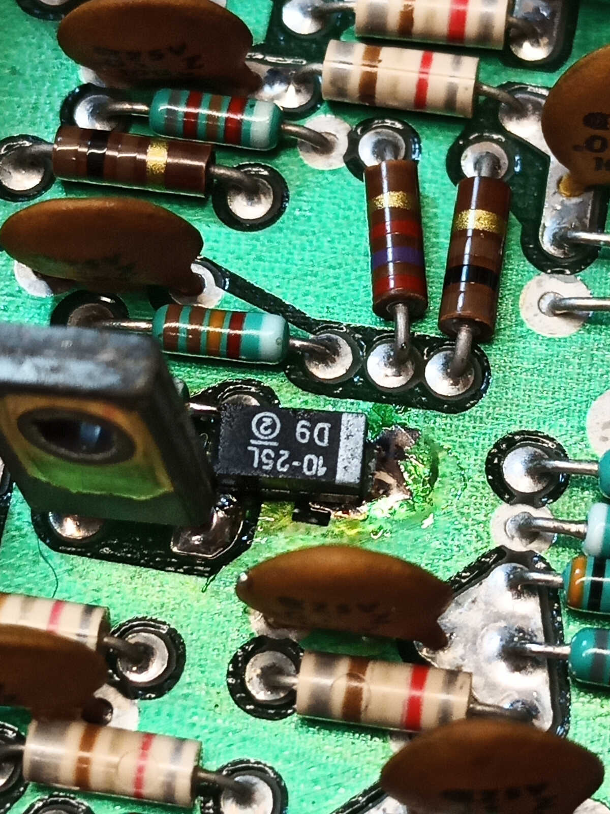
A short on the -12V supply was caused by a failed tantalum capacitor inside the A201 Source / Amplifier module.
After replacing the failed capacitor, the unit briefly worked again before another tantalum capacitor shorted and smoked. With many replacement capacitors fitted to avoid this sort of failure occurring again, the unit works correctly on the two lower frequency bands.
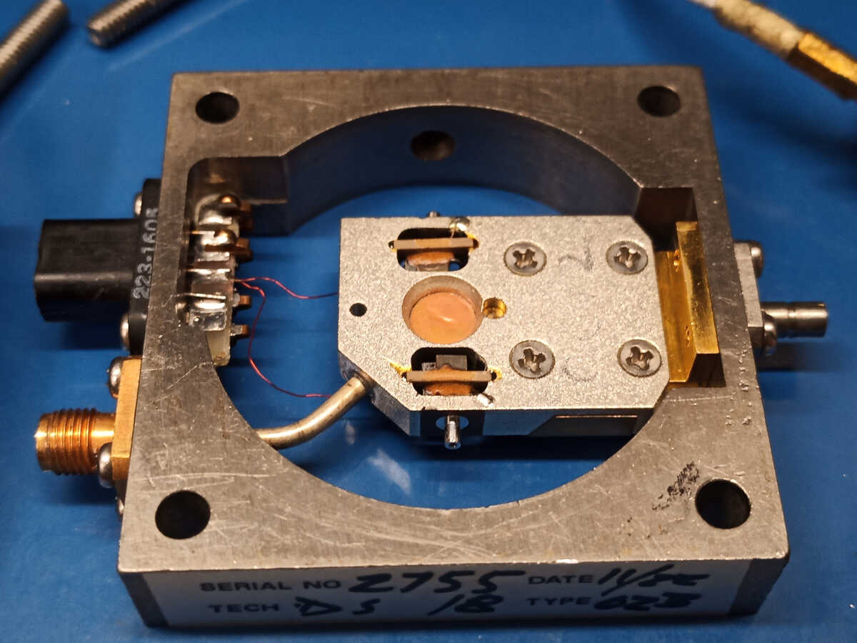
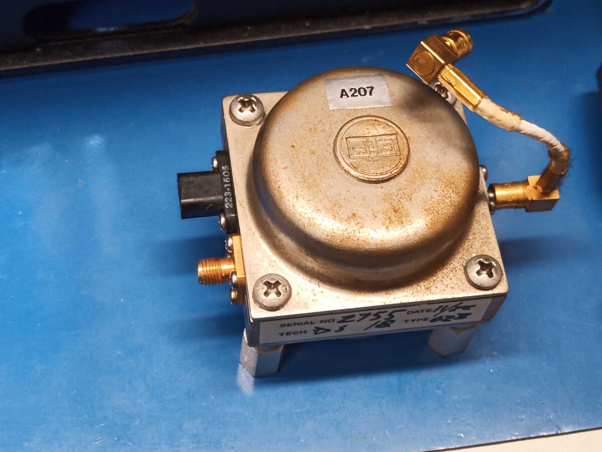
The highest frequency band is more complex, making use of a high frequency comb generator and YIG tunable filter selecting a harmonic of a 200MHz signal, then mixing this with the input signal to shift the input frequency to fall within the range of the 250MHz counter.
We found the tuning coil of the YIG tunable filter was not being driven, so the filter was heavily attenuating all the harmonics generated.

Solution
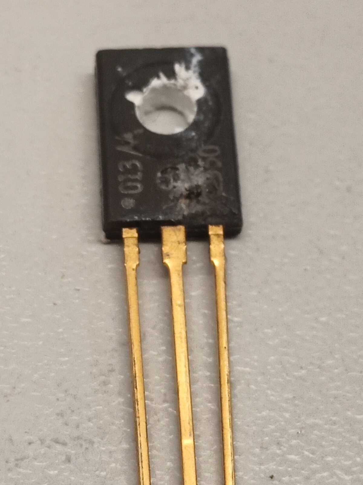
Two transistors in the current control loop for the YIG filter tuning were damaged. Once these transistors were replaced, the tunable filter was working correctly again.
The counter was initially displaying the count as 200MHz higher than the incoming test signal. For example, inputting 1GHz resulted in the display reading 1200MHz.
To correct this, adjustment of the slope and offset of the tuning coil drive current was needed to make the counter work correctly.
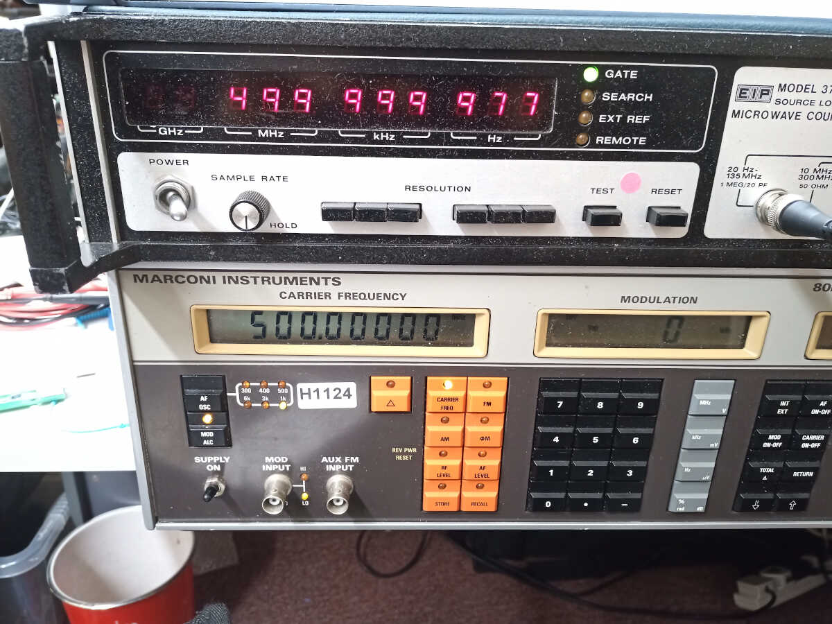
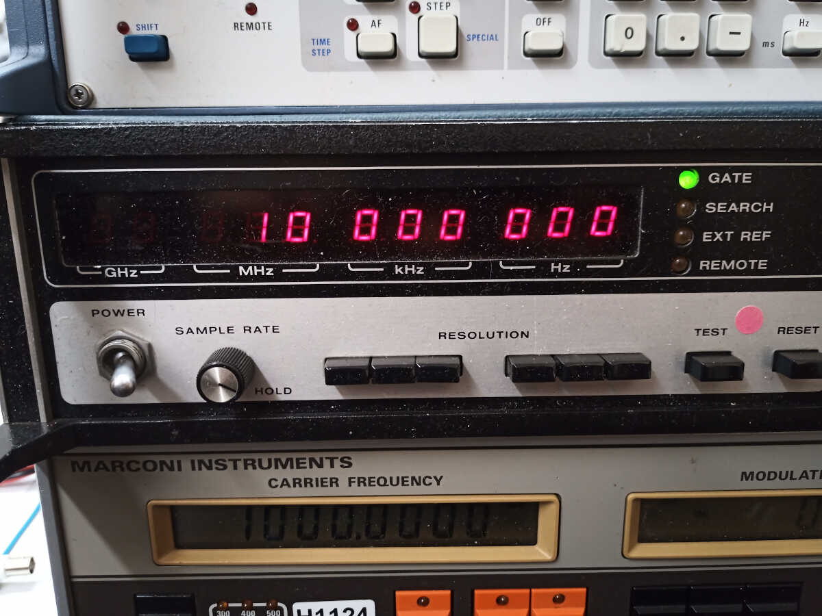
We tested the counter using an RF signal generator and then an 8 to 18 GHz YIG tuned oscillator to ensure it would count correctly across the entire operating range.
If you are experiencing similar issues and would like to discuss or request a quote, email us at
or call 01303 489 698.