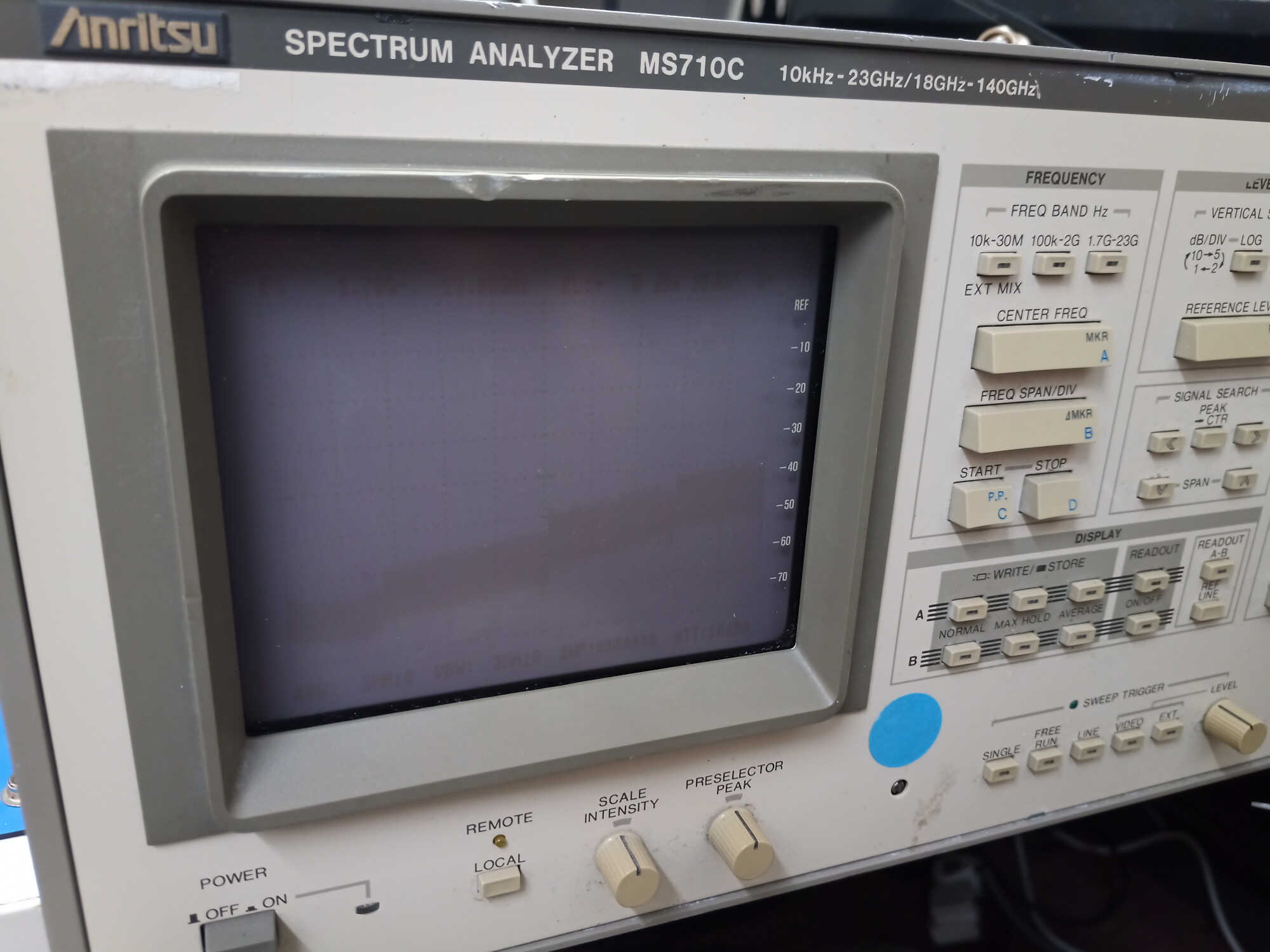
Anritsu MS710C spectrum analyser
Problem
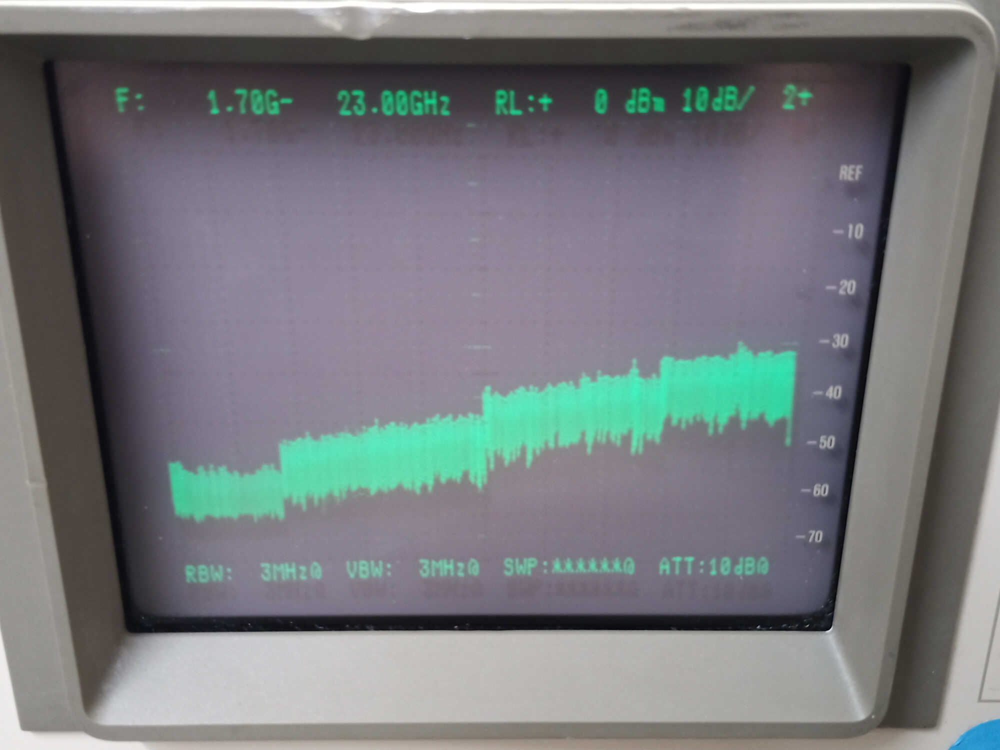
In initial testing it seemed that the spectrum analyser was working correctly on the lowest and highest frequency ranges. The 100 kHz to 2 GHz range would not display any input signal, only the noise floor was visible.
Measuring the local oscillator outputs and intermediate frequency outputs showed that the conversion was working as expected when the highest and lowest frequency ranges were operating, and that no conversion was happening in the 100 kHz to 2GHz range.
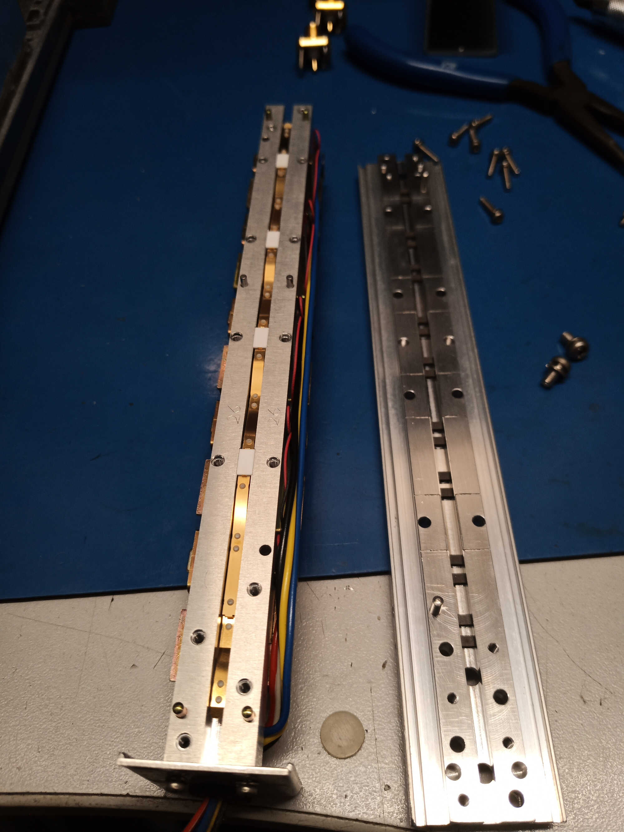
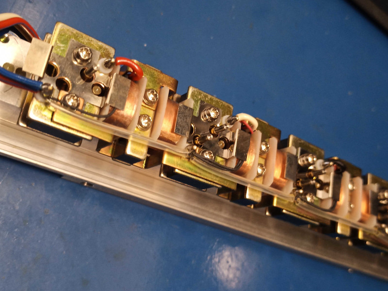
When selecting some input attenuator settings, the measured level was incorrect, indicating the attenuator was failing to switch.
Diagnosis
Testing the output of the 2nd Local Oscillator, it was apparent that the oscillator was working but the level was much lower than expected.
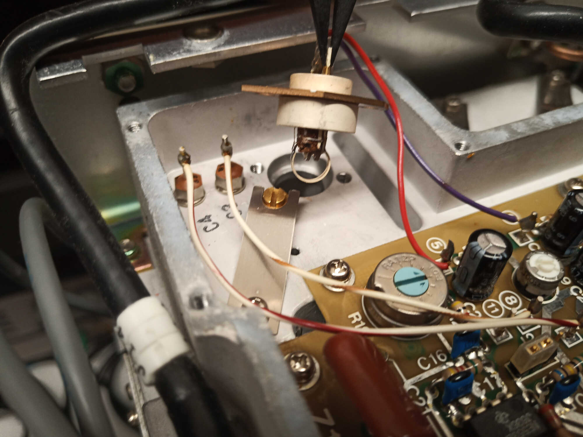
The low level meant that the down-conversion was not working as the mixer was not driven with sufficient power. The local oscillator is part of a phase locked loop (PLL) circuit and is mounted inside a tuned cavity. The cavity tuning was achieved with varactor diodes, driven by the PLL, which made it difficult to test the oscillator.
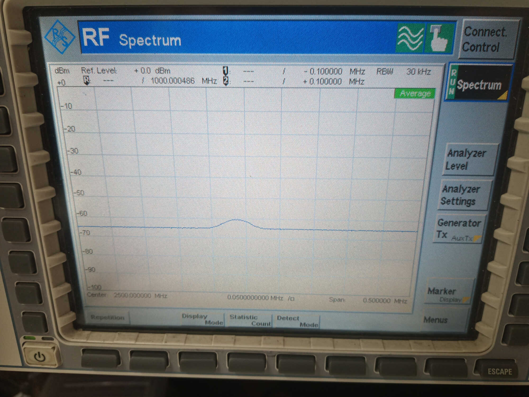
With the oscillator removed from the cavity it was possible to place an antenna near to the oscillator and measure the output with another spectrum analyser. The input attenuator was sticking and needed cleaning.
Solution
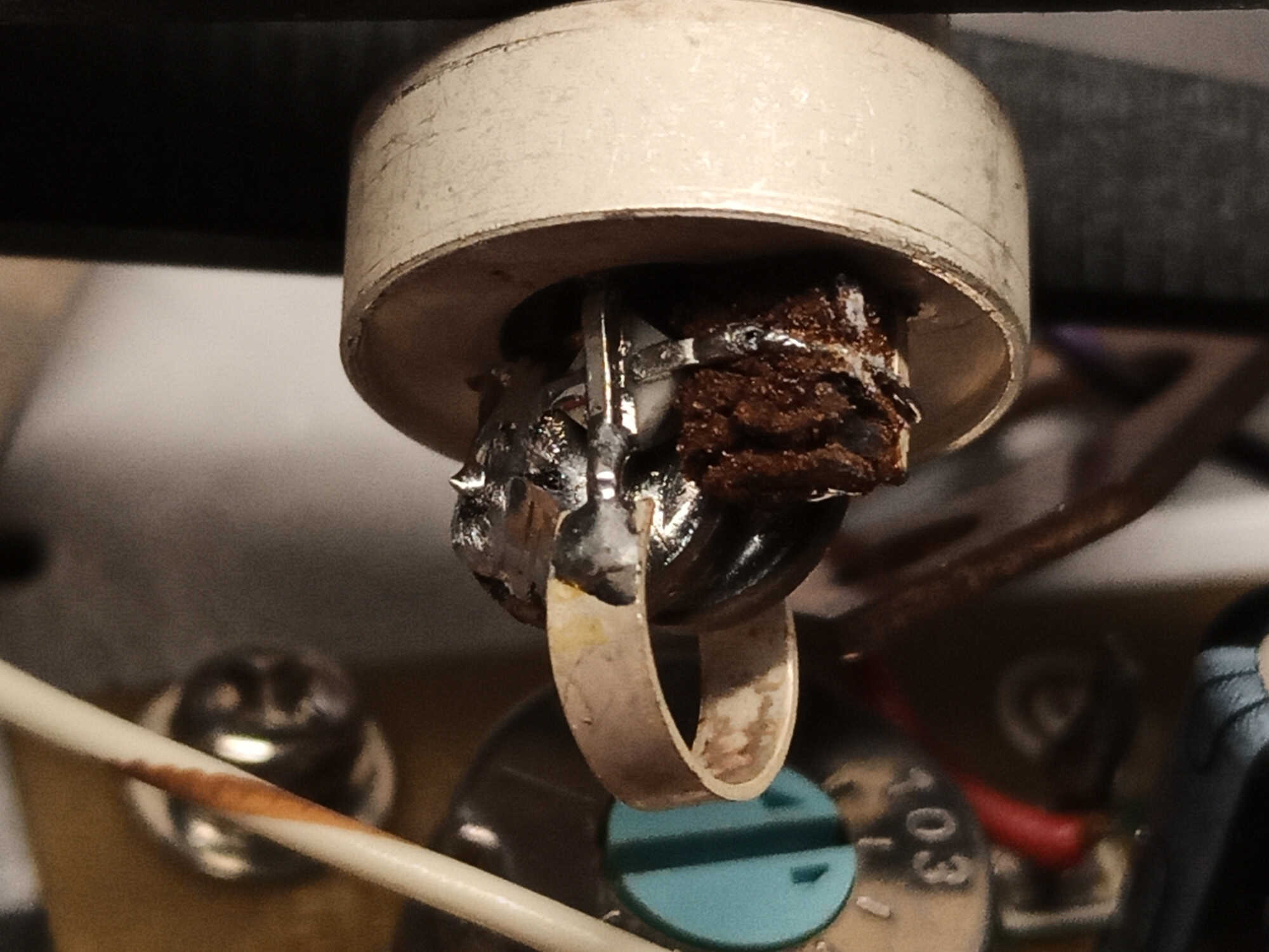
Carefully inspecting the oscillator revealed a cracked solder joint, with this repaired the oscillator output level was much higher.
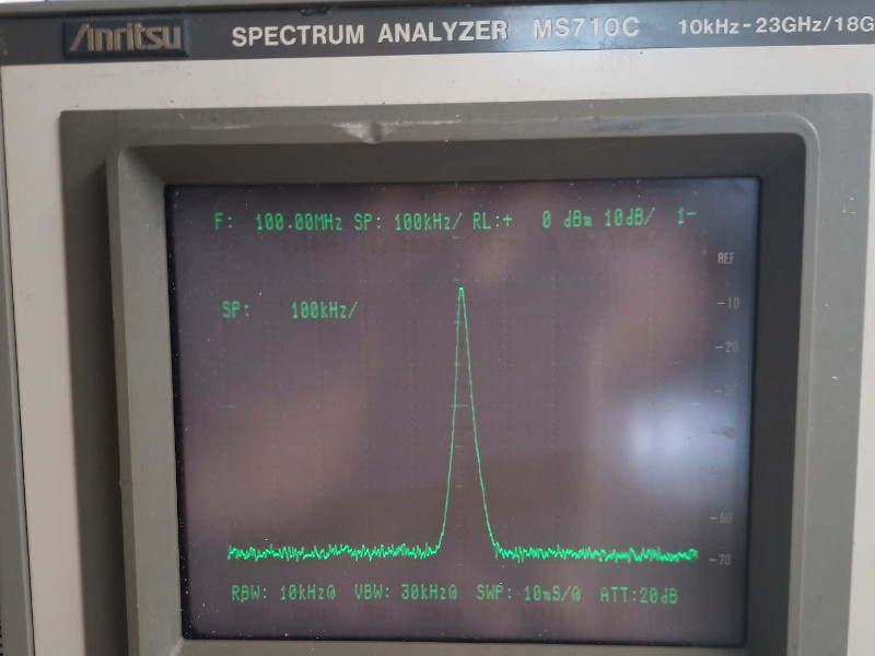
After placing the oscillator back into the cavity and adjusting the position for the highest output level at the local oscillator output, the down-conversion worked correctly.
Cleaning and lubricating the moving parts of the attenuator mechanism restored correct function and the measurement level now behaves as expected with all input attenuator settings.
If you are experiencing similar issues and would like to discuss or request a quote, email us at
or call 01303 489 698.